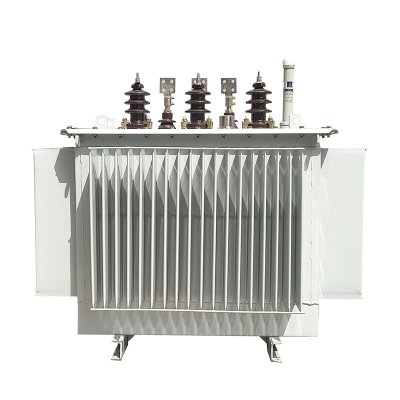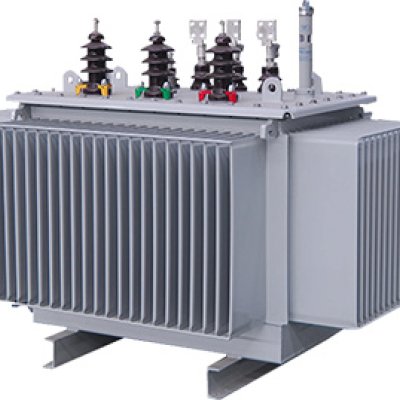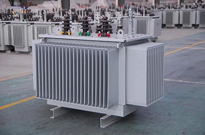


Oil-immersed transformer
**Oil-Immersed Transformer
User Manual**
Model No.: [Insert Model Number]
Revision: [Insert Revision Number]
Date: [Insert Date]
1. Introduction
This manual outlines the installation, operation, and maintenance procedures for [Manufacturer Name] oil-immersed transformers. Designed for reliability in demanding environments, these transformers utilize mineral oil for insulation and cooling. Strict adherence to this guide ensures safety and longevity.
2. Safety Warnings
DANGER:
Oil is flammable. No open flames or sparks near the transformer.
Always de-energize and ground the transformer before servicing.
Use PPE: oil-resistant gloves, safety goggles, and fire-retardant clothing.
Avoid skin contact with oil; wash immediately if exposed.
Comply with local environmental regulations for oil handling/disposal.
3. Installation
3.1 Pre-Installation Checks
Inspect for shipping damage (tank deformation, oil leaks).
Verify nameplate ratings (voltage, kVA, vector group).
Ensure oil level is within the sight gauge range (25°C ambient).
3.2 Site Requirements
Install on a flat, fire-resistant surface with drainage for oil containment.
Maintain clearances:
≥ 1.5 m from walls/obstructions.
≥ 3 m vertical clearance for bushings.
Provide firewalls if multiple units are installed.
3.3 Electrical & Mechanical Installation
Secure the tank to the foundation using anchor bolts (torque: [Insert Value] N·m).
Connect bushings according to the wiring diagram (Appendix A).
Ground the tank and neutral point with a 25 mm² copper conductor.
4. Oil Management
4.1 Oil Filling/Topping Up
Use only unused mineral oil meeting IEC 60296 standards.
Filter oil to ≤5 μm particles and ≤0.1% moisture content.
Fill slowly to avoid air bubbles; maintain oil level at 70% of the sight gauge.
4.2 Oil Testing
Perform dielectric strength test (≥30 kV/2.5 mm gap) before energization.
Annual dissolved gas analysis (DGA) to detect internal faults.
5. Operation
5.1 Commissioning
Confirm all connections and oil levels are correct.
Energize at no-load for 1 hour; check for unusual noise/vibration.
Gradually apply load (≤25% increments every 30 minutes).
5.2 Monitoring
Temperature Limits:
Winding (via RTD): Max 95°C (55°C rise over ambient).
Oil (top layer): Max 85°C.
Protection Devices:
Buchholz relay (alarms for gas accumulation; trips for severe faults).
Pressure relief device (activates at [Insert Value] kPa).
6. Maintenance
6.1 Routine Inspections
Daily (for critical systems): Check oil level, leaks, and temperature.
Monthly: Clean bushings, inspect silica gel in breather (replace if pink).
Annual: Test oil quality, tighten bushing connections, calibrate gauges.
6.2 Oil Replacement
Replace oil if:
Dielectric strength <25 kV/2.5 mm.
Acid number >0.2 mg KOH/g.
Dispose of used oil per EPA/local regulations.
7. Troubleshooting
| Symptom | Probable Cause | Action |
|---|---|---|
| Oil leakage | Gasket failure, loose bolts | Tighten/replace gasket |
| Buchholz alarm | Insulation degradation | Perform DGA, contact manufacturer |
| Overheating | Overload, blocked radiators | Reduce load, clean cooling fins |
8. Technical Data
| Parameter | Specification |
|---|---|
| Rated Power | [Insert kVA] |
| Primary Voltage | [Insert kV] |
| Secondary Voltage | [Insert kV] |
| Frequency | 50/60 Hz |
| Cooling Type | ONAN/ONAF (as specified) |
| Oil Capacity | [Insert Liters] |
| Impedance | [Insert %] |
9. Warranty & Contact
[Manufacturer Name] guarantees this product against defects for [X] years. For emergencies or technical support:
Hotline: [Insert Phone]
Service Email: [Insert Email]
Appendix A: Wiring Diagram & Terminal Layout
[Insert Diagram]
Appendix B: Recommended Spare Parts
Gaskets (Part No.: [Insert])
Buchholz relay (Part No.: [Insert])
Silica gel breather (Part No.: [Insert])
Note: Retain this manual for the transformer’s service life. Refer to IEC 60076 for additional standards.